7-segment display
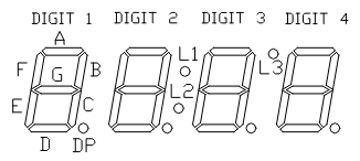
The GECKO5Education/Modular contain a 4-digit 7-segment display of type LTC-4627. This is a multiplexed 7-segment module. For reference for all descriptions below, the definitions from it’s data sheet below:
Using the 7-segment display
In this section you find a VHDL and Verilog top-level and the corresponding lpf-file that you can use for the 7-segment display.
Important
Although VHDL is case-insensitive, the lpf-file is not. Meaning that the port-names in the top-level entity need to be copied exactly in the lpf-file.
An example for a VHDL top-level entity is shown below:
library ieee;
use ieee.std_logic_1164.all;

entity toplevel is
  port ( displaySelect : out std_logic_vector( 2 downto 0 );
         nSegments     : out std_logic_vector( 7 downto 0 );
         ... );
end toplevel;
An example for a Verilog top-level is shown below:
module toplevel (
  output wire [2:0] displaySelect,
  output wire [7:0] nSegments,
  ...);
  ...
endmodule
The required entries in the lpf-file are:
LOCATE COMP "displaySelect[0]" SITE "C17";
LOCATE COMP "displaySelect[1]" SITE "D16";
LOCATE COMP "displaySelect[2]" SITE "C16";
LOCATE COMP "nSegments[0]" SITE "D14"; # Segment A/L1
LOCATE COMP "nSegments[1]" SITE "C13"; # Segment B/L2
LOCATE COMP "nSegments[2]" SITE "E14"; # Segment C/L3
LOCATE COMP "nSegments[3]" SITE "D15"; # Segment D
LOCATE COMP "nSegments[4]" SITE "C15"; # Segment E
LOCATE COMP "nSegments[5]" SITE "E15"; # Segment F
LOCATE COMP "nSegments[6]" SITE "B13"; # Segment G
LOCATE COMP "nSegments[7]" SITE "B15"; # Segment DP
IOBUF PORT "displaySelect[0]" PULLMODE=NONE IO_TYPE=LVCMOS33 DRIVE=4;
IOBUF PORT "displaySelect[1]" PULLMODE=NONE IO_TYPE=LVCMOS33 DRIVE=4;
IOBUF PORT "displaySelect[2]" PULLMODE=NONE IO_TYPE=LVCMOS33 DRIVE=4;
IOBUF PORT "nSegments[0]" PULLMODE=NONE IO_TYPE=LVCMOS33 DRIVE=4;
IOBUF PORT "nSegments[1]" PULLMODE=NONE IO_TYPE=LVCMOS33 DRIVE=4;
IOBUF PORT "nSegments[2]" PULLMODE=NONE IO_TYPE=LVCMOS33 DRIVE=4;
IOBUF PORT "nSegments[3]" PULLMODE=NONE IO_TYPE=LVCMOS33 DRIVE=4;
IOBUF PORT "nSegments[4]" PULLMODE=NONE IO_TYPE=LVCMOS33 DRIVE=4;
IOBUF PORT "nSegments[5]" PULLMODE=NONE IO_TYPE=LVCMOS33 DRIVE=4;
IOBUF PORT "nSegments[6]" PULLMODE=NONE IO_TYPE=LVCMOS33 DRIVE=4;
IOBUF PORT "nSegments[7]" PULLMODE=NONE IO_TYPE=LVCMOS33 DRIVE=4;
Important
Note the case-sensitivity of the lpf-file.
The tools require exactly one lpf-file, hence all assignments you use need to be in a single lpf-file.
The encoding of the displaySelect is shown in the table below:
displaySelect: |
digit selected: |
displaySelect: |
digit selected: |
|---|---|---|---|
\(000_b\) |
DIGIT 1 |
\(001_b\) |
DIGIT 2 |
\(010_b\) |
DIGIT 3 |
\(011_b\) |
DIGIT 4 |
\(100_b\) |
L1/L2/L3 |
other encodings |
all off |
The encoding of the bits of nSegments in dependance of displaySelect is shown in the table below (note \(-\) denotes a don’t care):
displaySelect: |
bit7: |
bit6: |
bit5: |
bit4: |
bit3: |
bit2: |
bit1: |
bit0: |
|---|---|---|---|---|---|---|---|---|
\(0--_b\) |
DP |
G |
F |
E |
D |
C |
B |
A |
\(100_b\) |
\(-\) |
\(-\) |
\(-\) |
\(-\) |
\(-\) |
L3 |
L2 |
L1 |
other encodings |
\(-\) |
\(-\) |
\(-\) |
\(-\) |
\(-\) |
\(-\) |
\(-\) |
\(-\) |
Important
The segments (nSegments) are active-low, meaning a logic 0 will light them up, and a logic 1 leaves them off.
Templates
To transform none-scanning high-active signals into a scanning version this VDHL or this Verilog module can be used. Both modules provide a scanning frequency of 1 kHz given the 50MHz clock as input.
Note
The inputs digit1, digit2, digit3, and digit4 are active-high and have the same bit definition as nSegments, as shown in the table above.
The inputs l1, l2, and l3 are active-high.
Summary
Below the table with all required information for the 7-segment display:
Name: |
FPGA pin: |
IO_TYPE: |
Active low/high |
Drive: |
|---|---|---|---|---|
displaySelect bit 0 |
C17 |
LVCMOS33 |
active high |
4 mA |
displaySelect bit 1 |
D16 |
LVCMOS33 |
active high |
4 mA |
displaySelect bit 2 |
C16 |
LVCMOS33 |
active high |
4 mA |
segments bit 0 |
D14 |
LVCMOS33 |
active low |
4 mA |
segments bit 1 |
C13 |
LVCMOS33 |
active low |
4 mA |
segments bit 2 |
E14 |
LVCMOS33 |
active low |
4 mA |
segments bit 3 |
D15 |
LVCMOS33 |
active low |
4 mA |
segments bit 4 |
C15 |
LVCMOS33 |
active low |
4 mA |
segments bit 5 |
E15 |
LVCMOS33 |
active low |
4 mA |
segments bit 6 |
B13 |
LVCMOS33 |
active low |
4 mA |
segments bit 7 |
B15 |
LVCMOS33 |
active low |
4 mA |