RGB-LED-array
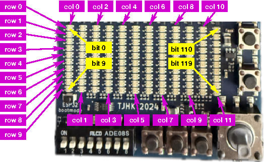
The GECKO5Education/Modular provide a 12x10 array of RGB-LED’s. As connecting all RGB-LED’s to the FPGA would require too much pins (12 x 10 x 3 = 360 pins), the RGB-LED array is implemented by row-column selection. For this purpose there is a column address that activates a single column in the array. For the selected column the RGB-LED’s in each row can be activated. By selecting each column one after the other, and activating the corresponding RGB-LED’s in the respective rows, a scanning array can be implemented.
The column address is a four-bit vector with following selection pattern:
column address: |
activated column: |
|---|---|
\(0000_b\) |
col 0 |
\(0001_b\) |
col 1 |
\(0010_b\) |
col 2 |
\(0011_b\) |
col 3 |
\(0100_b\) |
col 4 |
\(0101_b\) |
col 5 |
\(0110_b\) |
col 6 |
\(0111_b\) |
col 7 |
\(1000_b\) |
col 8 |
\(1001_b\) |
col 9 |
\(1010_b\) |
col 10 |
\(1011_b\) |
col 11 |
others |
display off |
Using the RGB-LED-array
In this section you find a VHDL and Verilog top-level and the corresponding lpf-file that you can use for the RGB-LED-array.
Important
Although VHDL is case-insensitive, the lpf-file is not. Meaning that the port-names in the top-level entity need to be copied exactly in the lpf-file.
An example for a VHDL top-level entity is shown below:
library ieee;
use ieee.std_logic_1164.all;

entity toplevel is
  port ( columnAddress : out std_logic_vector( 3 downto 0 );
         nRedRow       : out std_logic_vector( 9 downto 0 );
         nGreenRow     : out std_logic_vector( 9 downto 0 );
         nBlueRow      : out std_logic_vector( 9 downto 0 );
         ... );
end toplevel;
An example for a Verilog top-level is shown below:
module toplevel (
  output wire [3:0] columnAddress,
  output wire [9:0] nRedRow,
                    nGreenRow,
                    nBlueRow,
  ...);
  ...
endmodule
The required entries in the lpf-file are:
LOCATE COMP "columnAddress[0]" SITE "B6";
LOCATE COMP "columnAddress[1]" SITE "J3";
LOCATE COMP "columnAddress[2]" SITE "K3";
LOCATE COMP "columnAddress[3]" SITE "B17";
LOCATE COMP "nRedRow[0]" SITE "A7";
LOCATE COMP "nRedRow[1]" SITE "C6";
LOCATE COMP "nRedRow[2]" SITE "D13";
LOCATE COMP "nRedRow[3]" SITE "B12";
LOCATE COMP "nRedRow[4]" SITE "C11";
LOCATE COMP "nRedRow[5]" SITE "C10";
LOCATE COMP "nRedRow[6]" SITE "E9";
LOCATE COMP "nRedRow[7]" SITE "B9";
LOCATE COMP "nRedRow[8]" SITE "C8";
LOCATE COMP "nRedRow[9]" SITE "E7";
LOCATE COMP "nGreenRow[0]" SITE "C7";
LOCATE COMP "nGreenRow[1]" SITE "D6";
LOCATE COMP "nGreenRow[2]" SITE "E13";
LOCATE COMP "nGreenRow[3]" SITE "C12";
LOCATE COMP "nGreenRow[4]" SITE "E11";
LOCATE COMP "nGreenRow[5]" SITE "A11";
LOCATE COMP "nGreenRow[6]" SITE "A10";
LOCATE COMP "nGreenRow[7]" SITE "A9";
LOCATE COMP "nGreenRow[8]" SITE "D8";
LOCATE COMP "nGreenRow[9]" SITE "B8";
LOCATE COMP "nBlueRow[0]" SITE "E6";
LOCATE COMP "nBlueRow[1]" SITE "J4";
LOCATE COMP "nBlueRow[2]" SITE "D12";
LOCATE COMP "nBlueRow[3]" SITE "D11";
LOCATE COMP "nBlueRow[4]" SITE "B11";
LOCATE COMP "nBlueRow[5]" SITE "B10";
LOCATE COMP "nBlueRow[6]" SITE "D9";
LOCATE COMP "nBlueRow[7]" SITE "E8";
LOCATE COMP "nBlueRow[8]" SITE "A8";
LOCATE COMP "nBlueRow[9]" SITE "D7";
IOBUF PORT "columnAddress[0]" PULLMODE=NONE IO_TYPE=LVCMOS33 DRIVE=4;
IOBUF PORT "columnAddress[1]" PULLMODE=NONE IO_TYPE=LVCMOS33 DRIVE=4;
IOBUF PORT "columnAddress[2]" PULLMODE=NONE IO_TYPE=LVCMOS33 DRIVE=4;
IOBUF PORT "columnAddress[3]" PULLMODE=NONE IO_TYPE=LVCMOS33 DRIVE=4;
IOBUF PORT "nRedRow[0]" PULLMODE=NONE IO_TYPE=LVCMOS33 DRIVE=4;
IOBUF PORT "nRedRow[1]" PULLMODE=NONE IO_TYPE=LVCMOS33 DRIVE=4;
IOBUF PORT "nRedRow[2]" PULLMODE=NONE IO_TYPE=LVCMOS33 DRIVE=4;
IOBUF PORT "nRedRow[3]" PULLMODE=NONE IO_TYPE=LVCMOS33 DRIVE=4;
IOBUF PORT "nRedRow[4]" PULLMODE=NONE IO_TYPE=LVCMOS33 DRIVE=4;
IOBUF PORT "nRedRow[5]" PULLMODE=NONE IO_TYPE=LVCMOS33 DRIVE=4;
IOBUF PORT "nRedRow[6]" PULLMODE=NONE IO_TYPE=LVCMOS33 DRIVE=4;
IOBUF PORT "nRedRow[7]" PULLMODE=NONE IO_TYPE=LVCMOS33 DRIVE=4;
IOBUF PORT "nRedRow[8]" PULLMODE=NONE IO_TYPE=LVCMOS33 DRIVE=4;
IOBUF PORT "nRedRow[9]" PULLMODE=NONE IO_TYPE=LVCMOS33 DRIVE=4;
IOBUF PORT "nGreenRow[0]" PULLMODE=NONE IO_TYPE=LVCMOS33 DRIVE=4;
IOBUF PORT "nGreenRow[1]" PULLMODE=NONE IO_TYPE=LVCMOS33 DRIVE=4;
IOBUF PORT "nGreenRow[2]" PULLMODE=NONE IO_TYPE=LVCMOS33 DRIVE=4;
IOBUF PORT "nGreenRow[3]" PULLMODE=NONE IO_TYPE=LVCMOS33 DRIVE=4;
IOBUF PORT "nGreenRow[4]" PULLMODE=NONE IO_TYPE=LVCMOS33 DRIVE=4;
IOBUF PORT "nGreenRow[5]" PULLMODE=NONE IO_TYPE=LVCMOS33 DRIVE=4;
IOBUF PORT "nGreenRow[6]" PULLMODE=NONE IO_TYPE=LVCMOS33 DRIVE=4;
IOBUF PORT "nGreenRow[7]" PULLMODE=NONE IO_TYPE=LVCMOS33 DRIVE=4;
IOBUF PORT "nGreenRow[8]" PULLMODE=NONE IO_TYPE=LVCMOS33 DRIVE=4;
IOBUF PORT "nGreenRow[9]" PULLMODE=NONE IO_TYPE=LVCMOS33 DRIVE=4;
IOBUF PORT "nBlueRow[0]" PULLMODE=NONE IO_TYPE=LVCMOS33 DRIVE=4;
IOBUF PORT "nBlueRow[1]" PULLMODE=NONE IO_TYPE=LVCMOS33 DRIVE=4;
IOBUF PORT "nBlueRow[2]" PULLMODE=NONE IO_TYPE=LVCMOS33 DRIVE=4;
IOBUF PORT "nBlueRow[3]" PULLMODE=NONE IO_TYPE=LVCMOS33 DRIVE=4;
IOBUF PORT "nBlueRow[4]" PULLMODE=NONE IO_TYPE=LVCMOS33 DRIVE=4;
IOBUF PORT "nBlueRow[5]" PULLMODE=NONE IO_TYPE=LVCMOS33 DRIVE=4;
IOBUF PORT "nBlueRow[6]" PULLMODE=NONE IO_TYPE=LVCMOS33 DRIVE=4;
IOBUF PORT "nBlueRow[7]" PULLMODE=NONE IO_TYPE=LVCMOS33 DRIVE=4;
IOBUF PORT "nBlueRow[8]" PULLMODE=NONE IO_TYPE=LVCMOS33 DRIVE=4;
IOBUF PORT "nBlueRow[9]" PULLMODE=NONE IO_TYPE=LVCMOS33 DRIVE=4;
Important
Note the case-sensitivity of the lpf-file.
The tools require exactly one lpf-file, hence all assignments you use need to be in a single lpf-file.
The row select bits are active-low, meaning a logic 0 will light up the LED, a logic 1 forces the LED to be off.
Note
The bit-index of the RGB-vectors corresponds to the respective row in the array.
Templates
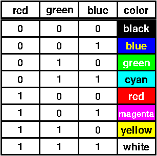
To be able to contol each LED in active-high mode, there is a module in VHDL and in Verilog that you can use as module in your top-level. Note that the bit-indexes are as shown in the picture above (in yellow/black). These modules use the 50 MHz clock source and provide a scanning frequency of 1 kHz. These modules can be used in either RGB-mode, or in single color mode.
The colors possible with the provided module are restricted to 8 colors, namely:
Summary
Below the table with all required information for the RGB-LED-array:
Name: |
FPGA pin: |
IO_Type: |
drive: |
Active low/high: |
Name: |
FPGA pin: |
IO_Type: |
drive: |
Active low/high: |
|---|---|---|---|---|---|---|---|---|---|
col A0 |
B6 |
LVCMOS33 |
4 mA |
active high |
col A1 |
J3 |
LVCMOS33 |
4 mA |
active high |
col A2 |
K3 |
LVCMOS33 |
4 mA |
active high |
col A3 |
B17 |
LVCMOS33 |
4 mA |
active high |
red row 0 |
A7 |
LVCMOS33 |
4 mA |
active low |
red row 1 |
C6 |
LVCMOS33 |
4 mA |
active low |
red row 2 |
D13 |
LVCMOS33 |
4 mA |
active low |
red row 3 |
B12 |
LVCMOS33 |
4 mA |
active low |
red row 4 |
C11 |
LVCMOS33 |
4 mA |
active low |
red row 5 |
C10 |
LVCMOS33 |
4 mA |
active low |
red row 6 |
E9 |
LVCMOS33 |
4 mA |
active low |
red row 7 |
B9 |
LVCMOS33 |
4 mA |
active low |
red row 8 |
C8 |
LVCMOS33 |
4 mA |
active low |
red row 9 |
E7 |
LVCMOS33 |
4 mA |
active low |
green row 0 |
C7 |
LVCMOS33 |
4 mA |
active low |
green row 1 |
D6 |
LVCMOS33 |
4 mA |
active low |
green row 2 |
E13 |
LVCMOS33 |
4 mA |
active low |
green row 3 |
C12 |
LVCMOS33 |
4 mA |
active low |
green row 4 |
E11 |
LVCMOS33 |
4 mA |
active low |
green row 5 |
A11 |
LVCMOS33 |
4 mA |
active low |
green row 6 |
A10 |
LVCMOS33 |
4 mA |
active low |
green row 7 |
A9 |
LVCMOS33 |
4 mA |
active low |
green row 8 |
D8 |
LVCMOS33 |
4 mA |
active low |
green row 9 |
B8 |
LVCMOS33 |
4 mA |
active low |
blue row 0 |
E6 |
LVCMOS33 |
4 mA |
active low |
blue row 1 |
J4 |
LVCMOS33 |
4 mA |
active low |
blue row 2 |
D12 |
LVCMOS33 |
4 mA |
active low |
blue row 3 |
D11 |
LVCMOS33 |
4 mA |
active low |
blue row 4 |
B11 |
LVCMOS33 |
4 mA |
active low |
blue row 5 |
B10 |
LVCMOS33 |
4 mA |
active low |
blue row 6 |
D9 |
LVCMOS33 |
4 mA |
active low |
blue row 7 |
E8 |
LVCMOS33 |
4 mA |
active low |
blue row 7 |
A8 |
LVCMOS33 |
4 mA |
active low |
blue row 9 |
D7 |
LVCMOS33 |
4 mA |
active low |